
 1
1


Material Considerations
1. Standard Nylon (PA12): The workhorse of SLS, PA12 delivers high tensile strength, impact resistance, and good chemical stability—ideal for functional prototypes and end‑use components.
2. Bio‑Based Nylon (PA11): Made from renewable castor oil, PA11 offers improved ductility and fatigue resistance over PA12, plus better performance in high‑temperature and chemical environments. Ideal for applications needing toughness and sustainability.
3. Reinforced Powders: Glass‑ or carbon‑filled nylons increase stiffness and dimensional stability. Great when you need beefier parts without adding bulk.
4. Elastomeric Powders (TPU): Flexible and fatigue‑resistant, TPU powders let you produce seals, gaskets, and wearable parts.
Design Rule of Thumb: Always check your material’s shrinkage rate (typically 0.3–0.7%) and anisotropy (XY vs. Z). At Hi3DP, our material data sheets guide you to the best choice for your application.
Wall Thickness & Internal Geometry
Minimum Wall Thickness:
Non‑structural walls: ≥ 0.8 mm
Load‑bearing walls: ≥ 1.2 mm
Maximum Solid Sections: Keep solid blocks under 5 mm in thickness to prevent excessive thermal stress and potential warping.
Hollowing & Powder Escape:
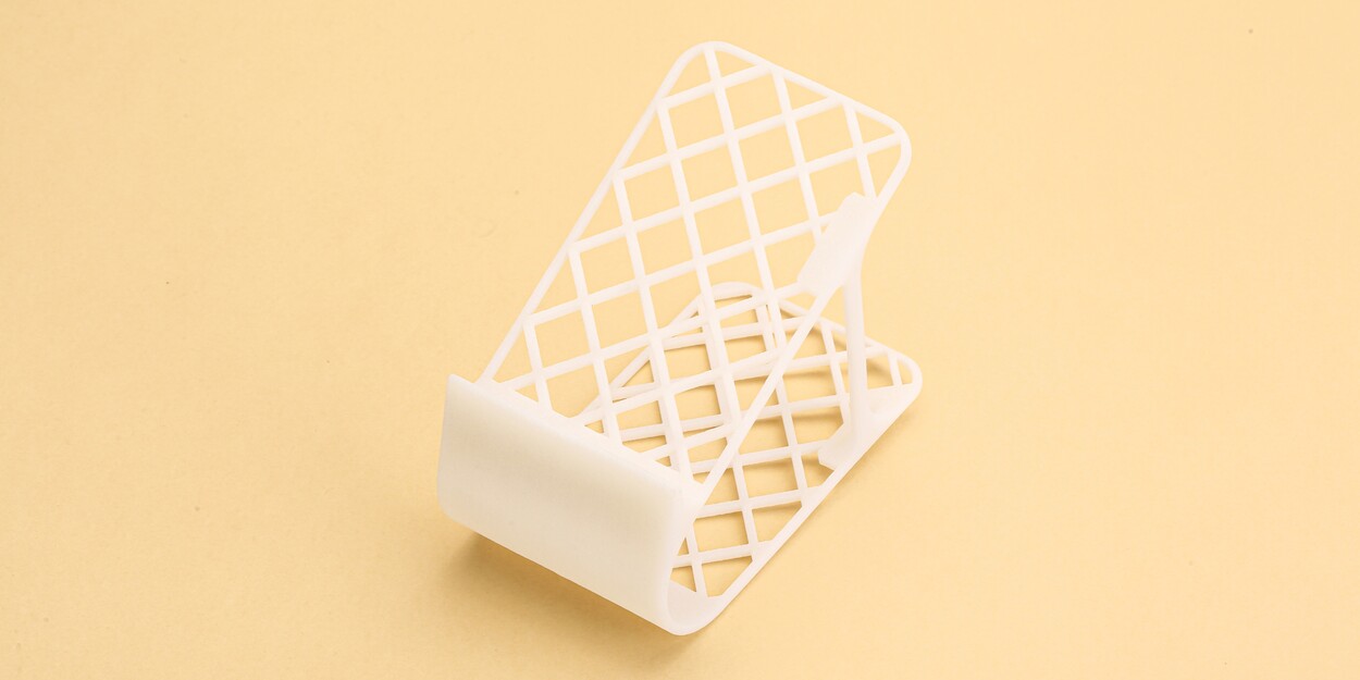
Use internal lattice or honeycomb infill to cut weight and cost.
Incorporate 2–3 mm diameter escape holes in cavities for efficient powder removal.
3D Printing Rule of Thumb: More material doesn’t always mean stronger parts—well‑designed internal geometry can boost performance while reducing powder usage.
Feature Resolution & 3D Printed Nylon Details
Small Features: The SLS process can resolve details down to ~0.5 mm, but yield drops for finer elements.
Embossed / Debossed Text:
Embossed: Minimum stroke width of 1.5 mm
Debossed: Debossed depth of at least 2 mm for clear visibility
Thin Features: Caps, clips, and snaps should be at least 0.8 mm thick. Anything thinner risks fusion failure.
Threaded Holes & Inserts:
For self‑tapping screws: design pilot holes ~M2 → 1.6 mm Ø
For heat‑set inserts: add chamfers and pockets to friction‑fit brass inserts
Dimensional Tolerances & Fits
General Tolerances:
Features < 50 mm: ± 0.3 mm
Features > 50 mm: ± 0.5 mm
Clearance Fits:
Snap‑fits: + 0.5 mm clearance per side
Press‑fits: – 0.1 mm interference (test on small prototypes)
Post‑Processing Impact: Bead‑blasting or sanding can remove up to 0.2 mm from external surfaces. If tight tolerances matter, build in extra allowance or opt for Hi3DP’s precision finishing services.
Selective Laser Sintering Tip: When in doubt, prototype the critical feature at full scale to validate fit.
Overhangs, Bridges & Support-Free Geometry
Self‑Supporting Angles:
Angles ≥ 30° from horizontal naturally support themselves in SLS.
For angles < 30°, expect rougher surfaces and potential sagging.
Bridging Gaps: Limit unsupported spans to ≤ 5 mm. For wider bridges, integrate micro‑ribs or thin walls underneath to stabilize powder.
No Supports Needed: One of the perks of SLS is support‑free geometry. Use that freedom to design complex interlocking parts or organic shapes without worrying about post‑print support removal.
Assembly Features
Snap‑Fits & Living Hinges:
Living hinge thickness: 0.4–0.6 mm nylon flex sections (durable for 20–30 cycles).
Cantilever snaps: design for 1 mm deflection under expected load.
Threaded Inserts:
Design pockets are slightly undersized for press‑fit brass or stainless inserts.
Hi3DP can install inserts post‑print for you, ensuring reliable repeat assemblies.
Interlocking Tabs & Slots: Use 0.3–0.5 mm clearance for sliding fits; tighten or loosen clearance based on prototype feedback.
Surface Finish & Post-Processing
As‑Built Texture: Characterized by fine grain “orange peel” surface; great for hiding minor layer artifacts.
Secondary Finishes:
Grit‑Blasting: Yields a uniform matte finish and accentuates detail.
Media‑Tumbling: Smooth edges but can slightly round sharp features.
Dye Infiltration / Painting: Adds color and weather resistance; perfect for branding or end‑use prototypes.
Design for Finishing: Avoid deep recesses where media can’t reach, and add 1 mm fillets to internal corners to prevent buildup.
Thermal Management & Warpage Control
Uniform Wall Thickness: Sudden thickness jumps lead to uneven cooling and warping. Aim for gradual transitions or ribs.
Ribs & Braces: 0.8–1 mm thick ribs every 20–30 mm stiffen panels and distribute thermal stress.
Build Nesting: When producing multiple parts, nest geometries of similar height to even out powder bed temperature.
Hi3DP Tip: Our pre‑build simulation flags potential hot spots so you can tweak your CAD model before printing.
Thermal Management & Warpage Control
Part Consolidation: Merge assemblies into single prints to reduce fasteners and assembly labor.
Lattice & Honeycomb Cores: Replace bulky solid volumes with lightweight lattices—save powder without sacrificing stiffness.
Orientation Trade‑Offs:
Taller builds → longer print time (more layers) but better Z‑axis resolution.
Flatter orientation → faster print but rougher bottom surface.
3D Printing Rule of Thumb: Balance height vs. surface quality: for large batches, optimize orientation for throughput; for single prototypes, prioritize aesthetics.
FAQs
Q: What’s the minimum feature size I can reliably print?
A: Aim for ≥ 0.5 mm for simple geometry; for text or thin walls, use ≥ 0.8–1.0 mm to ensure consistent fusion.
Q: How much does bead‑blasting affect dimensions?
A: Typically removes 0.1–0.2 mm of surface material. If you need tight tolerances, build in an extra 0.3 mm allowance.
Q: Can I print living hinges in nylon?
A: Yes—0.4–0.6 mm thick nylon flex sections can survive ~20–30 bending cycles. For more durability, design multi‑rib hinges.
Q: How do I remove powder from internal cavities?
A: Include 2–3 mm diameter escape holes. Hi3DP’s automated powder recovery also loosens trapped powder for manual cleaning.
Q: Do I need supports for overhangs?
A: No supports are required in SLS, but angles < 30° or bridges > 5 mm may show roughness. Add micro‑ribs for stability if needed.


